7. The board
This chapter introduces the board, its hardware and how to boot it.
7.1. Hardware
The hardware documentation of Hachiko can be found here:
http://downloads.architechboards.com/doc/Hachiko/download.html
7.2. Power-On
Hachiko takes the power from the micro-USB connector CN11 and/or the mini-USB connector CN2.
On connector CN2 you can also have the serial console, so, during your daily development use, you would just connect your workstation to the board using a mini-USB to connector CN2. If you connect some power ungry device to the board, you can give more power to the board by connecting your workstation (or a smartphone-like battery charger for example) to the board by means of a micro-USB cable to board connector CN11.
7.3. Serial Console
On Hachiko there is the dedicated serial console connector CN2
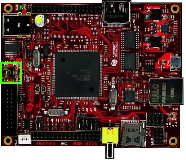
which you can connect, by means of a mini-USB cable, to your personal computer.
Note
Every operating system has its own killer application to give you a serial terminal interface. In this guide, we are assuming your host operating system is Ubuntu.
On a Linux (Ubuntu) host machine, the console is seen as a ttyUSBX device and you can access to it by means of an application like minicom.
Minicom needs to know the name of the serial device. The simplest way for you to discover the name of the device is by looking to the kernel messages, so:
- clean the kernel messages
Host
sudo dmesg -c
- connect the mini-USB cable to the board
- display the kernel messages
Host
dmesg
- read the output
[ 2912.634893] usb 3-4: >new full-speed USB device number 6 using xhci_hcd
[ 2912.658153] usb 3-4: >New USB device found, idVendor=0403, idProduct=6001
[ 2912.658160] usb 3-4: >New USB device strings: Mfr=1, Product=2, SerialNumber=3
[ 2912.658164] usb 3-4: >Product: Hachiko Rev. B
[ 2912.658167] usb 3-4: >Manufacturer: AVNET EMG ITALY
[ 2912.658169] usb 3-4: >SerialNumber: A6XGP6WP
[ 2912.660753] ftdi_sio 3-4:1.0: >FTDI USB Serial Device converter detected
[ 2912.660801] usb 3-4: >Detected FT232RL
[ 2912.660805] usb 3-4: >Number of endpoints 2
[ 2912.660809] usb 3-4: >Endpoint 1 MaxPacketSize 64
[ 2912.660812] usb 3-4: >Endpoint 2 MaxPacketSize 64
[ 2912.660815] usb 3-4: >Setting MaxPacketSize 64
[ 2912.661102] usb 3-4: >FTDI USB Serial Device converter now attached to ttyUSB0
As you can see, here the device has been recognized as ttyUSB0.
Now that you know the device name, run minicom:
Host
sudo minicom -ws
If minicom is not installed, you can install it with:
Host
sudo apt-get install minicom
then you can setup your port with these parameters:
+-----------------------------------------------------------------------+
| A -    Serial Device      : /dev/ttyUSB0                              |
| B - Lockfile Location     : /var/lock                                 |
| C -   Callin Program      :                                           |
| D -  Callout Program      :                                           |
| E -    Bps/Par/Bits       : 115200 8N1                                |
| F - Hardware Flow Control : No                                        |
| G - Software Flow Control : No                                        |
|                                                                       |
|    Change which setting?                                              |
+-----------------------------------------------------------------------+
        | Screen and keyboard      |
        | Save setup as dfl        |
        | Save setup as..          |
        | Exit                     |
        | Exit from Minicom        |
        +--------------------------+
If on your system the device has not been recognized as ttyUSB0, just replace ttyUSB0 with the proper device.
Once you are done configuring the serial port, you are back to minicom main menu and you can select exit.
7.4. Bootstrap
In the latest release only bootmode 3 is supported by Hachiko board. That is the board boots from the serial flash memory connected to the SPI multi I/O bus. To enable bootmode 3 the jumpers J4, J5 and J6 must be respectively in position 0, 1 and 1. When set for bootmode 3, the bootloader (U-Boot) must be flashed on the serial NOR at address 0x18000000 (SPI multi I/O bus space). Hachiko boards already have the latest version of U-Boot flashed on SPI NOR at factory time.
For more information:
7.5. Write to NOR
7.5.1. Using PARTNER-Jet
- Write to serial flash:
- Execute PARTNER-Jet_ARM_V5_71b.exe
- Create a new project
- Copy “JETARM.CFG” and “usrflash_arm.MON” from flash directory to created project.
- Push power on button of PARTNER-JET
- Write U-boot image data for serial flash boot to 0x18000000.
7.5.2. Using ULINK2
To use ULINK2, DS-5 from ARM Ltd. and binary writing tool provided from Renesas are needed. As for the way to obtain these tools, please ask Renesas electronics sales representative. After the installation of DS5 and binary writing tool, please go to the next step.
- Writing to serial flash:
- Clear RZ_A1H_spibsc_boot_init\Debug\RZ_A1H_spibsc_boot_init.bin\ directory in DS-5 workspace.
- Rename U-boot image file for serial flash boot u-boot.bin as VECTOR_TABLE and put it on the above directory.
- Run DS-5.
- Connect ULINK2 to the board and poweron the board.
- Click script tag and double click RZ_A1H_sflash_boot_user.ds
- SPIBSCBoot.zip file containing the DS-5 workspace, the script file and a launcher configuration (download link)
- DS-5 (preferred and tested version: DS500-BN-00003-r5p0-15rel1)
- Setup of the environment and first run:
- Install the DS-5 and use the activation code found here http://ds.arm.com/renesas/rza-starter-kit/ to enable the Renesas compiler when a valid licence is asked the first time DS-5 is started
- Unzip the content of SPIBSCBoot.zip. Three more files should be available: Connection_Only.launch, Workspace.zip and script.zip. Unzip also Workspace.zip and script.zip
- Start DS-5 and import into workspace all the three projects ([File] >> [Import Existing Projects into Workspace]) taking care of select [Copy projects into workspace] when importing
- Import also the launch configuration (file Connection_Only.launch) ([File] >> [Import] >> [Launch configurations])
- Copy the script directory into workspace directory and copy only the script RZ_A1H_sflash_boot_user.ds in the workspace directory (outside the script dir)
- Open [Run] >> [Debug Configurations...] menu, then click on [DS-5 Debugger] >> [Connction_only]. In the [Connection] tab select [Renesas]/[RZ/A Series-R7S72100]/[Bare Metal Debug]/[Debug of Coretex-A9 via ULINK2] and press the [Browse] button to identify and select the attached debugger. Press Apply to save changes.
- Rename u-boot.bin file as VECTOR_TABLE and copy it in RZ_A1H_spibsc_boot_init\Debug\RZ_A1H_spibsc_boot_init.bin\ directory inside the workspace
- Connect the ULINK2 and power on the board. Select again [Run] >> [Debug Configurations...] menu, click on [DS-5 Debugger] >> [Connction_only] and on the Debug button.
- When the DS-5 Dubug perspective is open, in the [Script] tab of DS-5 import the script RZ_A1H_sflash_boot_user.ds
- Pause the microprocessor with the button in the toolbar and double-click on the script to run it
- When the download script runs, the flash downloader is launched and a message is shown in the [Application Console]. Answer Y to the first question and N to the second one
- When downloading finishes, it is possible to disconnect from target
- For all the subsequent times it will be enough:
- Open the DS-5
- Switch to DS-5 Debug perspective
- Select the launcher from the [Debug control] tab
- Press the [Connect to Target] button in the toolbar
- Double click on the script in the [Script] tab
- Answer Y and N to the two questions in the [Application Console]
- Disconnect from the target using the [Disconnect from the Target] button in the toolbar
For a more detailed description of the entire process, see:
- Renesas Application Note: Example of Downloading to Serial Flash Memory Using the Semihost Function of ARM DS-5”
- Renesas Applicaton Note: Example of Booting from Serial Flash Memory
Note
7.6. U-Boot
To check if the board is correctly programmed, connect the board to a terminal emulator on your computer. To see how this can be achieved please refer to section serial_console_label.
If everything is setup correctly you should be able to see the bootstrap process and the U-Boot output. In particular, as soon as the board is powered a countdown is started and displayed on the serial output. If a key is pressed before the countdown expires the autoboot stops, otherwise Linux is loaded from USB or SPI NOR.
On Hachiko board you can boot using the USB or the serial NOR. During the boot process, if U-Boot detects a correct kernel and rootfs on the USB drive it will boot from this USB device, otherwise it will switch to SPI NOR. In case no correct linux kernel is detected, the boot stops in the U-Boot console.
For a brief documentation about U-Boot:
7.7. Boot from USB
Booting from USB requires that an USB pen drive is prepared with all the files needed for booting Linux and that it is correctly partitioned.
Important
The only USB port that it is possible to use for booting is the USB port at the bottom of the USB connector.
7.7.1. USB partitioning
The USB pen driver is required to have one single EXT2 partition with a start sector of the partition below the 63rd sector. It is possible to use tools as fdisk or cfdisk to partition the USB drive.
Before use these commands you need unmount the device:
sudo umount /path/to/your/USB/device/partitionAfter that you can use the following commands:
sudo cfdisk /path/to/your/USB/deviceAs alternative it is possible to use the sfdisk tools to have the partition correctly aligned to the first sector:
sudo sfdisk /path/to/your/USB/device << EOF
0,
EOFsudo mkfs.ext2 /path/to/your/USB/device/partition7.7.2. USB content
When booting from USB, U-Boot expects to find a valid single EXT2 partition in the USB pen drive containing the rootfs. Moreover U-Boot needs to find in /boot directory a valid kernel image and a valid DTB file respectively named uImage and rza1-hachiko.dtb.
When using Yocto to generate the rootfs we need to extract the compressed rootfs found in
/home/architech/architech_sdk/architech/hachiko-tiny/yocto/build/tmp/deploy/images/hachikoin the partition on the USB and copy the kernel in /boot/uImage and DTB file in /boot/rza1-hachiko.dtb.
Briefly, to have a bootable USB stick after having compiled an image with Yocto:
- Create one EXT2 partition in the USB stick
- Extract the content of your .tar.bz2 rootfs tarball file in the EXT2 partition
- Copy uImage to /boot
- Copy uImage-rza1-hachiko.dtb to /boot and rename it as rza1-hachiko.dtb
At this point it is possible to boot Linux by inserting the USB pen drive in the correct USB port and power on the board.
7.8. Boot from NOR
When no USB device is attached or the kernel image is not valid, U-Boot tries to boot from SPI NOR. In Hachiko board the NOR is required to contain all the needed files in the first serial flash memory on channel 0.
Note
A valid NOR Linux image is programmed at factory time in Hachiko NOR, so it is possible to start using Hachiko board right away.
7.8.1. NOR Partitioning
The serial flash memory is divided into 5 partitions according to the following scheme (the base address is 0x18000000):
0x18000000-0x18080000 spibsc0_loader  (offset: 0x00000000)
0x18080000-0x180c0000 spibsc0_bootenv (offset: 0x00080000)
0x180c0000-0x184c0000 spibsc0_kernel  (offset: 0x000c0000)
0x184c0000-0x18500000 spibsc0_dtb     (offset: 0x004c0000)
0x18500000-0x1c000000 spibsc0_rootfs  (offset: 0x00500000)
spibsc0_loader: contains u-boot (u-boot.bin)
spibsc0_bootenv: contains u-boot environment
spibsc0_kernel: contains the Linux kernel (uImage)
spibsc0_dtb: contains the DTB file (rza1-hachiko.dtb)
spibsc0_rootfs: contains the rootfs
7.8.2. NOR content
To write in NOR and replace or update the content of the NOR partitions you can go through U-Boot or Linux. It is strongly recommended to use Linux for writing new data in NOR partitions, especially when no external SDRAM is available.
7.8.2.1. Using U-Boot [not recommended]
Using U-Boot for writing or updating data in SPI NOR is not advisable especially when no external SDRAM is available.
Warning
The operation is prone to failure, use it at your own risk.
The process of writing data in serial NOR using U-Boot goes through 3 main steps: 1) load the file to write in a temporary RAM location, 2) erase data on the NOR partition and 3) write the new data.
- Assuming you have the file on the USB pen drive you have to load it in RAM using the following commands:
usb start
ext2load usb 0 0x20000000 /path/to/your/u-boot.bin
The output from the command is also the size of the file loaded, info useful for step (3).
RAM ranges:
0x20000000 - 0x20A00000
Please, note that while spibsc0_loader, spibsc0_kernel, and spibsc0_dtb partitions of the flash memory contain raw data respectively for u-boot.bin, uImage and rza1-hachiko.dtb, whereas partition spibsc0_rootfs contains raw data for the filesystem that, in our case, is a JFFS2 image. That is, when writing a new rootfs in spibsc0_rootfs partition it is needed to use the image file .jffs2 generated by Yocto.
- To erase data on the NOR partition;
sf erase $OFFSET $SIZEwhere $OFFSET is the partition offset and $SIZE its size in bytes.
- To write new data:
sf write $RAM_ADDR $OFFSET $SIZEwhere $RAM_ADDR is the temporary RAM location holding our file (tipically 0x20000000), $OFFSET is the partition offset and $SIZE is the file size in bytes as obtained by the output of the command ext2load in step (1).
For more informations about flash managing with U-Boot refer to:
7.8.2.2. Using Linux
To use linux for writing or updating data on the serial NOR you are going to need MTD utils. It is possible to compile a small image containing the MTD utils with Yocto by means, for example, of image core-image-minimal-mtdutils that can be generated by Bitbake with this command line:
bitbake core-image-minimal-mtdutilsWarning
In Linux, the process is made easier by the MTD framework that remap each NOR partition to a different device file. In particular:
/dev/mtd0: spibsc0_loader
/dev/mtd1: spibsc0_bootenv
/dev/mtd2: spibsc0_kernel
/dev/mtd3: spibsc0_dtb
/dev/mtd4: spibsc0_rootfs
Again the process goes through 2 steps: (1) erasing the content of the serial NOR partition and (2) write the new data.
- To erase the content of the partition the tool flash_erase can be used. For raw files as u-boot.bin, uImage or rza1-hachiko.dtb, the tool can be used as follow:
flash_erase /path/to/your/mtd/device 0 0This command completely erases the content of the partition. For the root file system the command is slightly different, since being spibsc0_rootfs a JFFS2 partition, it requires proper formatting, so for mtd4 device you need to run this command:
flash_erase -j /dev/mtd4 0 0- To write the new data on the serial NOR the tool flashcp is used. Again for raw file the simple syntax is:
flashcp -v /path/to/your/file /path/to/your/mtd/deviceFor rootfs we have two different ways to write data in spibsc0_rootfs partition:
- Using the image file .jffs2 generated by Yocto
flashcp -v /path/to/your/image/file.jffs2 /dev/mtd4- If you wish to use the image file .tar.bz2 instead, you need to mount the partition and decompress the file content in place.
mount -t jffs2 mtd4 /mnt/
tar xv -C /mnt/ -f /path/to/your/image/file.tar.bz2
umount /mnt/
For more information on how to manage flash storage with Linux:
7.9. Network
The network PHY is provided by Renesas’s chip 60610 (U6). Within Linux, you can see the network interface as eth0.
If you want that configuration to be brought up at boot you can add a few line in file /etc/network/interfaces, for example, if you want eth0 to have a fixed ip address (say 192.168.0.10) and MAC address of value 1e:ed:19:27:1a:b6 you could add the following lines:
auto eth0
iface eth0 inet static
    address 192.168.0.10
    netmask 255.255.255.0
    hwaddress ether 1e:ed:19:27:1a:b6